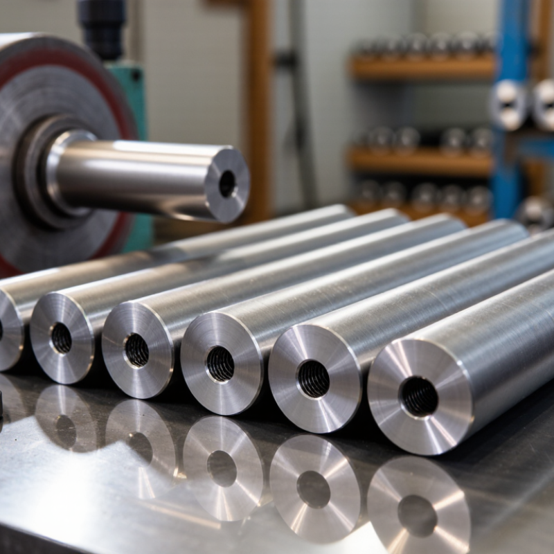
Round Carbide Rods are valued because their shape supports reliable, repeatable cutting-tool production. A cylindrical blank can be ground into drills, end mills, reamers, and other tools with precise shank dimensions. Its symmetry also helps maintain balance at high spindle speeds. That matters when a tool meets dense metal and produces a fine, continuous chip.
The carbide itself is typically a hard tungsten-carbide phase bonded with cobalt. This combination can resist abrasion and retain a cutting edge under demanding conditions. It is not indestructible. Excessive heat, poor alignment, or sudden impact can still cause chipping. Toolmakers must match grade, geometry, and operating conditions to the job.
A proposed expert-style line for this draft: “A rod is only a starting point; its value comes from consistent material and careful grinding.” This is original wording, not a verified quotation. It is attributed here to fictional carbide-tooling specialist Dr. Lena Hart and should not be presented as a real expert’s statement.
The round form makes stock convenient to inspect, store, and machine. It also gives manufacturers flexibility when producing tools in different diameters and lengths. Small variations matter. A slight runout can affect finish, tool life, and dimensional accuracy. Buyers should check grade, tolerance, straightness, and supplier documentation, rather than relying on appearance alone. In practice, no single rod suits every cutting task. That is easy to overlook.
Round carbide rods are cylindrical blanks used to make drills, end mills, reamers, and other cutting tools. They are usually made from tungsten carbide powder mixed with a metallic binder, often cobalt. The carbide provides hardness and wear resistance. The binder adds toughness and helps reduce brittle failure.
Manufacturing begins with carefully measured powders. The mixture is milled until its particles are evenly distributed. A spray-drying step forms free-flowing granules for pressing or extrusion. The compact then looks solid, but it remains fragile. It must be handled gently.
During debinding, heat removes forming agents. Sintering follows in a controlled furnace, often near 1,400°C. The material shrinks significantly as its pores close. Manufacturers measure this change to maintain the required diameter and density. Some rods receive pressure-assisted sintering for improved internal consistency.
After sintering, diamond grinding creates the final round surface. Diameter tolerance, straightness, grain structure, and hardness are checked before machining. In production, even a small pore or uneven binder area can affect tool life. That detail is easy to underestimate. A rod may appear flawless under ordinary light yet perform poorly under interrupted cutting. Processing is highly controlled, but it is not perfect. Tool designers still need to match the rod’s grade, diameter, and toughness with the workpiece material and cutting conditions.
Round carbide rods are commonly used as blanks for drills, end mills, and other rotary cutting tools. Their hardness helps an edge resist abrasion when it meets tough workpieces. The material is typically made from tungsten carbide grains held together by a metallic binder, often cobalt. The exact blend matters. It affects hardness, toughness, and how the rod behaves during grinding.
Hardness alone does not explain their usefulness. Carbide has high compressive strength and stiffness, so a properly supported tool can hold its shape under cutting forces. That helps maintain a consistent diameter and a clean cutting profile over repeated passes. The round form also gives toolmakers a practical starting point: a rod can be ground into flutes, relief angles, and a precise shank. In a workshop, those details show up as steady rotation and less visible edge wear.
There are trade-offs. Carbide is hard, but it can chip or fracture under sudden impact, especially if the tool is poorly supported. It is not unbreakable. Heat, feed rate, and workpiece material still matter, and coolant may be useful in some operations. A harder grade may resist wear well but feel less forgiving. Choosing a rod is therefore a balance, not a simple search for maximum hardness.
A round carbide rod gives toolmakers a predictable starting shape for drills, end mills, and reamers. Its circular cross-section is easy to hold and rotate during grinding. This helps maintain concentricity between the shank and cutting features, especially when tight runout limits matter. Small details matter. A slight centerline error can make a tool vibrate or cut unevenly.
The rod’s uniform profile also lets designers choose different diameters and lengths before adding flutes, relief angles, or coolant passages. The blank stays simple. In shop practice, this flexibility can reduce setup changes when several tool sizes share a similar design. However, a round rod is only raw geometry; it does not create a cutting edge on its own. Grinding must define the edge, and carbide’s stiffness does not make it immune to chipping. Designers can sometimes focus too much on hardness and overlook flute spacing or edge support. Those choices affect chip flow, heat, and how the tool behaves in a specific material. A secure fit in the holder matters, too.
Round carbide rods are widely used to make solid end mills, drills, reamers, and rotary burrs. A toolmaker grinds the cylindrical blank into cutting edges, flutes, and a shank suited to the machine. End mills may have two or more flutes for slotting or side milling. Carbide drills use a pointed tip and spiral flutes to guide chips out of the hole. Reamers refine an existing hole, while burrs shape edges and small contours. Small details matter.
The rod form gives manufacturers a consistent base for these different geometries. Its hardness helps cutting edges resist wear when machining tough materials, and its stiffness can support accurate work at small diameters. But carbide is hard, not indestructible. A sharp edge can chip if the tool is poorly supported or fed too aggressively. That distinction is easy to overlook. The right rod grade, tool geometry, and coating depend on the work material and cutting conditions; no single carbide tool suits every job. Even a well-made cutter may perform poorly if its flute design cannot clear chips from a deep cut.
Example flute counts for common solid-carbide tool designs
Round carbide rods are ground into solid cutting tools such as end mills, drills, reamers, and taps. Their rigidity and wear resistance make them useful for precision machining. The flute counts shown are common examples, not fixed specifications; designs vary with the tool, material, and machining application.
Selecting a round carbide rod starts with the material being cut and the tool’s job. Hardness alone is not enough. Fine-grain carbide can help maintain a sharp edge and resist wear, while a tougher grade may better withstand interrupted cuts or vibration. The binder content also affects this balance. A rod chosen only for maximum hardness may chip when it meets a hard spot in the workpiece.
Dimensions matter just as much. Rod diameter and length must suit the finished tool, with enough material for grinding without excessive waste. Check straightness and surface condition; a slight bend can complicate precise grinding and affect runout. Small details count. Coolant access, cutting speed, and tool geometry influence heat and stress at the edge. In a narrow drill, for example, poor chip evacuation can raise temperature even when the rod grade seems suitable.
Performance should be checked under real operating conditions. Record tool life, edge wear, and whether failure comes from gradual wear or sudden chipping. These clues can point to different adjustments, such as changing the grade, feed, or edge preparation. I would not treat a catalog specification as a guarantee. Machine rigidity, grinding quality, and operator setup can shift results, sometimes more than expected. A short controlled trial can reveal that mismatch before a larger batch is made.
| Selection Factor | Typical Data or Range | Effect on Tool Performance | Selection Guidance |
|---|---|---|---|
| Material Composition | Tungsten carbide (WC) with approximately 6–15% cobalt binder | WC provides hardness and wear resistance, while cobalt improves toughness and resistance to impact. | Use lower cobalt levels for high wear resistance and higher cobalt levels when interrupted cuts or vibration are expected. |
| Carbide Grain Size | Fine: about 0.2–0.8 µm Medium: about 0.8–1.5 µm Coarse: above about 1.5 µm |
Fine grains generally increase hardness and edge retention. Coarser grains usually improve fracture toughness. | Select fine-grain rods for finishing and abrasive materials; choose medium- or coarse-grain rods for heavy or interrupted cutting. |
| Hardness | Commonly about 89–94 HRA, depending on grade and grain size | Higher hardness helps resist flank wear, crater wear, and abrasive damage during continuous cutting. | Prioritize higher hardness for stable setups and non-interrupted operations. Avoid selecting hardness alone when shock loading is present. |
| Transverse Rupture Strength | Typically about 2,000–4,000 MPa for cemented-carbide grades | Higher strength reduces the risk of chipping or breakage when the tool experiences bending, vibration, or interrupted engagement. | Choose a higher-strength rod for roughing, interrupted cuts, long overhangs, or less rigid machines. |
| Density | Approximately 14.4–15.1 g/cm³ for many WC–Co grades | Density provides a useful indication of composition consistency and binder content. | Compare measured density with the supplier’s grade specification to identify composition variation or manufacturing defects. |
| Tool Diameter | Common solid-rod diameters range from less than 1 mm to more than 20 mm | Diameter affects bending stiffness, tool strength, chip space, cutting reach, and achievable feed rate. | Use the largest diameter that fits the workpiece and holder to reduce deflection and improve stability. |
| Length-to-Diameter Ratio | Short tools are generally more rigid; long-reach tools have greater deflection risk | Deflection can cause dimensional errors, vibration, premature edge failure, and poor surface finish. | Keep the tool overhang as short as practical. For long-reach applications, consider a tougher grade and reduced cutting loads. |
| Straightness | Precision rods are commonly specified with straightness limits in the range of approximately 0.02–0.10 mm per metre | Poor straightness can increase runout, imbalance, uneven edge loading, and vibration during rotation. | Use tighter straightness specifications for small-diameter, high-speed, and finishing tools. |
| Surface Quality | Ground or polished surfaces are preferred for finished tool blanks; surface defects should be minimized | Cracks, pits, and grinding damage can act as stress concentrators and initiate tool failure. | Inspect the rod surface before grinding and reject pieces with visible cracks, chips, deep scratches, or discoloration. |
| Internal Coolant Configuration | Solid rods, single-hole rods, and multi-hole rods are commonly available | Internal coolant can improve chip evacuation and heat control, especially in deep holes and high-feed machining. | Choose solid rods for general applications and coolant-hole designs when chip evacuation or thermal control is critical. |
| Edge Preparation | Sharp, honed, or chamfered cutting edges | Sharp edges reduce cutting forces, while honing and chamfering improve edge strength and resistance to chipping. | Use sharper edges for finishing and softer materials; use a small hone or chamfer for roughing and interrupted cuts. |
| Workpiece Material | Typical applications include steel, cast iron, stainless steel, non-ferrous alloys, and abrasive composites | Different workpiece materials generate different levels of heat, abrasion, adhesion, and impact loading. | Match carbide hardness, cobalt content, grain size, coating, and geometry to the workpiece’s hardness and cutting behavior. |
| Operating Stability | Rigid machine and holder versus vibration-prone or interrupted conditions | Stable conditions favor harder, wear-resistant grades; unstable conditions increase the need for toughness. | For vibration or interrupted cuts, reduce tool overhang, improve clamping, lower cutting loads, and select a tougher rod grade. |

| Note: The values shown are typical industry ranges for cemented-carbide rods and may vary by grade, manufacturing process, tool geometry, and test method. Final selection should be verified against the rod manufacturer’s technical specification and the actual cutting conditions. | |||